Ultrashort electron pulses
Ultrashort electron pulses
Introduction
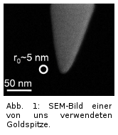 In this experiment, we are investigating and improving the possibilities for controlling electron movements on ultrashort time and length scales. The medium-term goal here is to manipulate short electron flashes in a targeted manner so that they can be used, for example, to make the fastest changes in nanoparticles visible. In order to control the generation of the electrons spatially very precisely, we use sharp metal tips with a tip radius of only 5 to 10nm (Fig. 1). Electrons are released from these in a very short time window of only a few femtoseconds (fs) when a few-cycle laser pulse hits the tip.
The laser system
To generate these ultrashort light pulses, we use a titanium:sapphire regenerative amplifier ('Spitfire Pro XP' from Spectra-Physics) with a downstream multi-stage non-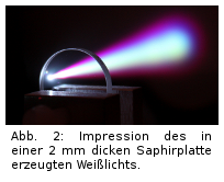 collinear optical parametric amplifier (NOPA), built in collaboration with a friendly research group led by Giulio Cerullo in Italy. In the NOPA, part of the energy of the regenerative amplifier system (120fs pulse duration, 800µJ pulse energy, 5kHz repetition rate) is used to create a supercontinuum ('white light') in a thin sapphire plate (Fig. 2). This supercontinuum is amplified in the second part of the NOPA in the visible and near-infrared spectral range. This allows the generation of coherent light pulses that have a broad spectrum and thus support a short pulse duration of less than 10fs (Fourier transform limitation). The two amplified pulses are frequency-mixed in a final step (difference frequency generation) to produce a pulse in the infrared range (~1700nm).
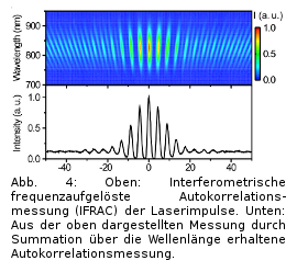 We compensate almost completely for the chirp introduced by various components in the NOPA with the help of 'chirped mirrors'. The time profile of the laser pulses is characterised by an interferometric frequency-resolved autocorrelation (IFRAC) measurement (Fig. 4). Thus, we generate and measure pulses that are only 17fs long and thus last only a good two oscillations of the electric field. At the same time, the phase position of the carrier frequency relative to the envelope (carrier envelope
 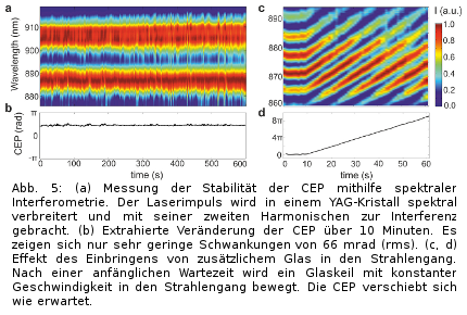 phase, CEP) is passively fixed by the choice of amplifier stages. Although the CEP is unstable in the amplifier system, these fluctuations, since they occur equally in both NOPA stages, can just cancel each other out during the subsequent difference frequency generation (Fig. 5a,b). By exploiting dispersion in glass, the previously passively stabilised CEP can be altered (fig. 5c,d). Small wedges of fused silica with an angle of 4 degrees can be pushed into the beam, whereby the shift of just over 1mm at a central wavelength of 1700nm just results in a CEP shift of 2pi.
Experiment General
The pulses are then focused with a Cassegrain lens in a vacuum chamber (1e-7 mbar) on a spot with a diameter of about 2µm (Fig. 6). At the laser focus is one of our gold tips. The laser field causes electrons to overcome the binding tip potential 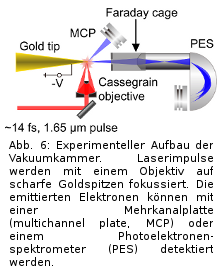 . Since, at the laser wavelength we use, individual photons do not have sufficient energy to allow the electron to overcome the bond by absorption, significantly higher laser intensities are required; ionisation can then take place via the simultaneous absorption of several photons (multiphoton ionisation, MPI). In our case, between 7 and 8 photons are needed to release an electron from the tip. If the laser intensity is increased further, processes are more likely in which more photons than necessary are absorbed, so that the kinetic energy of the emitted electrons increases (above threshold ionisation, ATI). Finally, the intensity can be increased to the point where the photon image no longer quite fits and electrons can tunnel out of the tip due to their wave properties when the laser field periodically 'bends' the potential barrier (strong-field ionisation).
Emission angle constriction
The emission of electrons from such gold tips occurs at a rather large angle of about 30 degrees. Such a large angle has so far been observed independently of the regime (MPI, ATI, strong field) in which the emission takes place. Recently, we investigated the strong-field emission of electrons in more detail and observed that the fastest electrons in the strong-field regime are emitted at a much smaller angle of only 12 degrees. We were able to show this angular dependence by measuring the kinetic energy of the emitted electrons with angular resolution using a photoelectron spectrometer (Fig. 7). Simulations 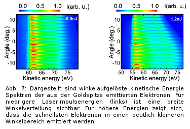 show that electrons emitted at the beginning of a half cycle of the laser field can leave the near field of the tip within this half cycle and are hardly influenced by the following oscillations of the electric field. Due to the short time in the near field of the tip, these electrons are significantly less influenced by the curvature of the tip surface and thus less deflected laterally. This leads to the observed narrowing of the emission angle of the fastest electrons.
Current
We are currently trying to use the knowledge we have already gained to move closer to realising an ultrafast electron microscope. Help is always welcome, so we would be happy to hear from interested bachelor's/master's/doctoral candidates to discuss possible projects after a lab tour.
We are currently looking for a student to work with us on a bachelor's or master's thesis in our group.