Confocal Laser Scanning Microscopy (CLSM)
Contact
Mailing Address
Visitors
Confocal Laser Scanning Microscopy (CLSM)
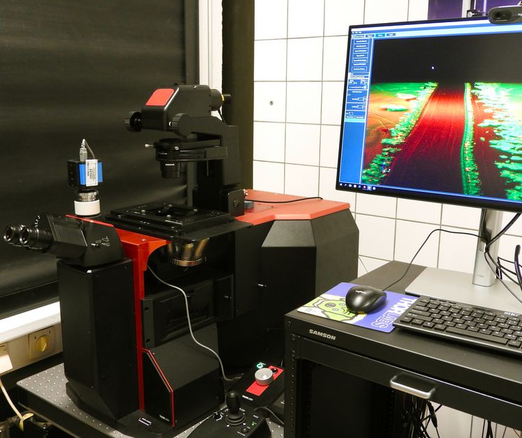
Instrumentation
Thorlabs Veneto
Four laser lines for excitation (405, 488, 561 and 640 nm)
Multiband notch filter allows adaption to different fluorescent dyes without change of filter set.
The 640 nm laser line may be used for reflection measurements.
Operation Principle
Principle and Application
Confocal laser scanning microscopy (CLSM) uses a laser for raster scanning a sample. A small aperture (pinhole) in fron tof the detector blocks light that is emitted above and below the focal plane near the sample. This (unfocused) light is obstructed from reaching the detector and cannot contribute blurring of the image. The sample can be scanned in several layers each offset by an incremental change in the working distance. The intensity data recorded as a function of x,y,z space coordinates can be used to obtain high-resolution images and three-dimensional reconstructions from surfaces. The key feature of confocal microscopy is its ability to produce blur-free images of thick specimens at various depths. An example is the demonstration of defects at a recessed microelectrode in Figure 2.

Technical Details
The confocal principle is illustrated schematically in Figure 3. A collimated laser beam (green) is reflected by a dichroic beam splitter and focused onto the specimen by the objective lens of the microscope. In our instrument a multiband notch filter is used. The emitted, fluorescent light (red, with longer wavelength) is collected by the objective lens, passes through the beam splitter and is focused into a small pinhole (i.e., the confocal aperture) to eliminate all the out-of-focus light (i.e., all light coming from below or above the focal plane near the sample). The sample is raster scanned using a xy scanning unit, which is placed between dichroic filter and objective lens. The change in the z coordinate is made by a motorized sample table.
A zthree-dimensional image can be reconstructed by combining twodimensional images of subsequent layers within a stack.
Reflection measurements are possible if the dichroic filter does not completely block the wavelength used for excitation. In our setup, the 640 nm-line allows this working mode.
