Supercontinuum polarisation pulse shaping
Contact
Prof. Dr. Matthias Wollenhaupt
Carl von Ossietzky Universität Oldenburg
Faculty V - Institute of Physics
Carl-Von-Ossietzky-Str. 9-11
D-26129 Oldenburg
Germany
Tel.: +49-441-798-3482
room: W2 1-101
matthias.wollenhaupt@uol.de
Supercontinuum polarisation pulse shaping
An ultrashort laser pulse can be shaped as required in the laboratory using spectral phase modulation. The process is based on transparent liquid crystal displays (LCD), whose individual pixels can be controlled and thus manipulated specifically with regard to the refractive index.
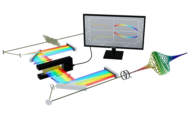
In order to shape a laser pulse using such a display, it must first be broken down into its spectral components. To do this, the laser pulse (top left in the figure, white) is directed onto a grating whose reflection angles are frequency-dependent. This results in a spatial decomposition of the laser pulse into its frequency components, or a Fourier transformation. The fanned-out beam is then collimated and directed into the so-called Fourier plane in which the above-mentioned display (black box) is located. By manipulating the refractive indices of the liquid crystal pixels (golden elements), a phase shift of the frequency components is then achieved (hence the term spectral phase shaping). The frequency components are then reunited by a mirrored structure and a shaped pulse is created.
With a pulse shaper consisting of two liquid crystal displays whose optical axes are oriented at an angle of +-45° to the polarisation of the incident laser pulse, both the spectral phase and the polarisation of the laser pulse can be shaped. By using polarisers behind the displays, the polarisation shaping can be translated into amplitude modulation. A few examples of spectral femtosecond pulse shaping are visualised below.
Pulse shaping with linear spectral phase functions
In the examples shown here, the variation of the parameter Φ of the phase function φ(ω)=Φ⋅ω is shown. The phase function is shown on the left-hand side of the monitor. There are also two polarisers behind the pulse shaper, which are used to filter out two spectral components from the overall spectrum. By varying the phase functions for the blue and red components, the two components can be delayed with respect to each other. Mathematically, this is described by the so-called group delay T(ω) (right-hand side of the monitor). The group delay is given by the derivative of the spectral phase: T(ω)=dφ(ω)/dω = Φ.
The pulse shaping with a linear phase function of the form φ(ω)= Φω is shown above. If this phase function is now shifted by the centre wavelength ω₀ of the laser field to be formed, i.e. the phase function φ(ω)= Φ(ω-ω₀) is used, the pulse is not interferometrically shifted in time, as would be the case with arms of different lengths in an interferometer. Instead, only the so-called envelope is shifted.
Pulse shaping with quadratic spectral phase functions
In the example shown above, the variation of the parameter Φ of the phase function φ(ω)=Φ⋅ω² is visualised. Applying this phase creates a so-called chirped pulse in which the frequency components ω are linearly shifted against each other. As a result, they no longer occur simultaneously, but one after the other, whereby - depending on the sign of Φ - the chirp (chirping) can occur upwards (from low to high frequencies) or downwards (from high to low frequencies). The figure shows the progression from blue to red and thus from high to low frequencies. This is known as a downchirp.
The linear progression of the frequency follows mathematically from the group delay T(ω). This is given by the derivative of the applied spectral phase: T(ω)=dφ(ω)/dω = Φ⋅ω. This linear shift of the frequencies is shown in the figure above directly behind the liquid crystal display by the coloured blocks.